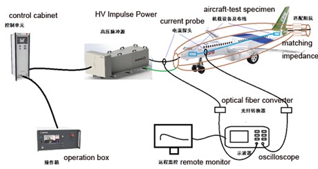
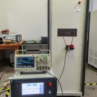
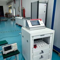
Automatic control and measurement system- The computer can communicate with the oscilloscope, remotely set the oscilloscope, read the oscilloscope waveform, and automatically calculate the waveform parameters;
Each part has wheels at the bottom, easy for movement;
Accurate measurement and smooth waves;
User friendly, easy operation and maintenance;
Considerate safet measures, such as emergancy stop button, green and red light, door safety interlock, etc.
Platform Lightning Test System is designed to inject lightning test currents into an aircraft or into large components or sections thereof (such as engines or wings) for the purpose of experimentally determining the voltages and currents that would be induced on electrical wiring inside an equivalent structure when it is struck by lightning.
The test system shall consist of generators designated to perform Platform level aircraft test defined in SAE ARP 5416 and MIL-STD-464.
serial number | name | Model | quantity | Introduction to the device |
1 | H-wave generator | SXIC-10H | 1 set | H waveform: 0.245μs±20%/4μs±30%;
Max. load is 30μH, output:0.1~1 kA; Insulation material: N2 or SF6; Discharge switch: Adjustable gas spark switch; Based on PLC + touch screen control scheme; It can realize the automatic control of the whole test process; Contains air compression control unit; |
2 | A-wave generator | SXIC-03A | 1 set | A waveform: 6.4μs ±20% /69μs±30%
The output is from 1kA to 3 kA when testing a large system with 30 μH; Discharge switch: Gas ignition switch Based on PLC + touch screen control scheme It can realize the automatic control of the whole test process; |
3 | Oscilloscope | MDO34 3-BW-100 | 1 unit | Bandwidth: 100MHz
Sample rate: 2.5Gs/s Four-channel |
4 | Multi-channel digital acquisition system | SXFA3024 | 3 sets | Frequency range: 200MHz
Number of channels: 4 channels Communications: Fiber optics Power supply: battery, more than 4 hours It can communicate the probe with the measurement and analysis software, and the host computer analyzes and monitors the waveform |
5 | Current probe | C225 | 1 set | Self-integrating current sensor
The maximum value is 5kA Frequency range: 100Hz-5MHz Measurement ratio: 0.01V/A |
6 | Current probe | C325S | 1 unit | Self-integrating current sensor
The maximum value is 5kA Frequency range: 100Hz-5MHz Measurement ratio: 0.1V/A |
7 | Current probe | C313S | 3 sets | Self-integrating current sensor
The maximum value is 2kA Frequency range: 100Hz-10MHz Measurement ratio: 0.1V/A |
8 | Current probe | C312S | 1 set | Self-integrating current sensor
The maximum value is 1kA Frequency range: 100Hz-10MHz Measurement ratio: 0.1V/A |
9 | Attenuators | A10 | 1 set | Ratio: 10:1 |
10 | Measurement and analysis systems | iMAS3520 | 1 set | The computer can communicate with the oscilloscope, remotely set the oscilloscope, read the oscilloscope waveform, and automatically calculate the waveform parameters |
11 | Remote control unit | IMCS2000 | 2 sets | Touch screen operation;
Control the two generators; Equipped with an emergency stop button |
12 | Surface current probes | SX30-50-10M | 2 pcs | Maximum peak current: 5000A
Sampling factor: 0.001V/A |
13 | Inductor matching box | customize | 1 set | The multi-segment inductance is adjustable, and the overall inductance is guaranteed to be 30μH during external testing |
14 | Voltage probe | V60DP | 1 | Ratio:1000:1 |
15 | Cage design | Prepared by the buyer | ||
16 | Impedance box | SXDZ-08 | 1 | To avoid resonant |