High Current Physical Damage Test System, Lightning Direct Effects Test System on Aircraft, Component ABCD

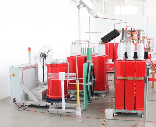
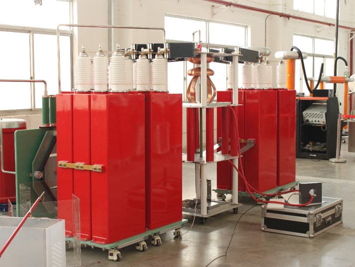
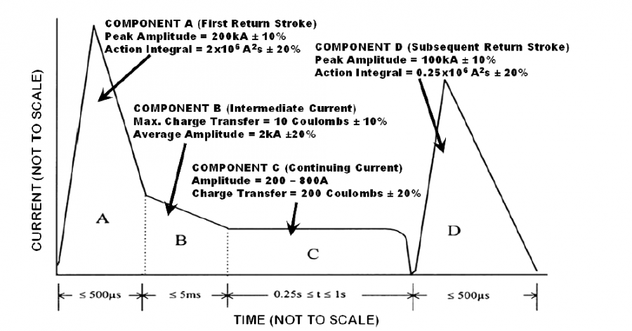
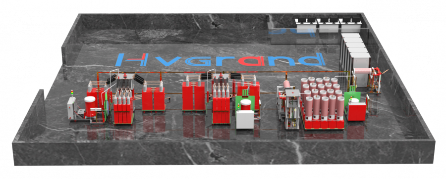
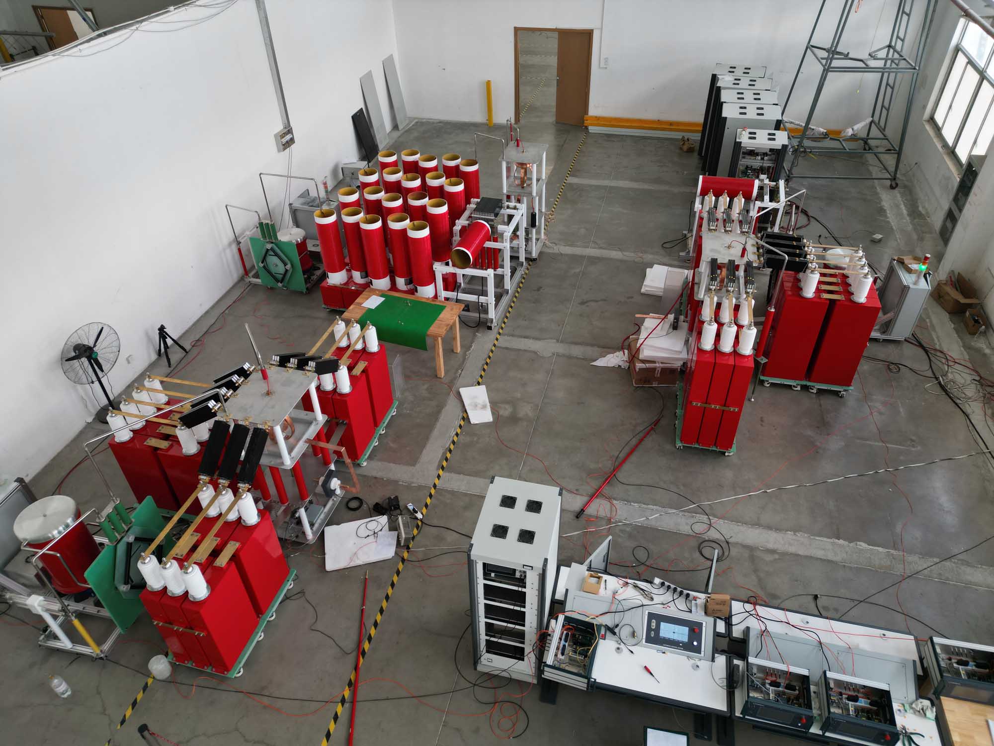
High Current Test System is used to conduct high current physical damage testing for lightning direct effects as per RTCA DO-160 Section 23, SAE ARP5416B Section 5, MIL-STD-464D and SAE-ARP-5412C Section 6. It can output current test components A,Ah, A/5, B,C,C*,D, which can be applied individually or as a composite of two of more components together in one test.High current physical damage test is used to determine the damage that may occur to the test object during a lightning channel attachment to or near the test object.

Additional Product Information

Features & Benefits
  1. Digital Crowbar Switch for unipolar component Awith fast response, longer lifetime and perfectly catching the peak point;
  2. Four individual current generators can be used individuallyor together by one main control system to achieve the ABCD waves following an order defined by the operator.
  3. Possible configurations of induced current tests are as follows:A Only, B Only, C Only, D Only, A+B, Ah+B, D+B, A+B+C, A+B+C*,D+B+C, D+B+C*, Ah+B+C, Ah+B+C*, A/5+B+C*,A+B+C+D.
  4. Possible configurations of arc entry tests are as follows:A+B+C, A+B+C*, B+C+D, D+B+C*, Ah+B+C, Ah+B+C*, A/5+B+C*, A+B+C+D.
  5. Coupling units are adopted forcomponent B and C generators to avoid the negative influence from component A and D;
  6. With user friendly 15’ color touch paneland automatic computerised measurement system;
  7. Component C generator is featured with less power supply requirement (50kVA) and improved arc pulling ability (a plasma constant current source scheme);
  8. Enhanced safety measures
  9. Increased discharge stability: Component A and D:gap sphere without igniton discharge-gap to max distance- no self discharge; Component B: high power SCR digital switch, without air interference;
  10. Different load range: from 0~7μH for selection.
Applications

High Current Test System is used to conduct high current physical damage testing for lightning direct effects as per RTCA DO-160 Section 23, SAE ARP5416B Section 5, MIL-STD-464D and SAE-ARP-5412C Section 6. It can output current test components A,Ah, A/5, B,C,C*,D, which can be applied individually or as a composite of two of more components together in one test.

High current physical damage test is used to determine the damage that may occur to the test object during a lightning channel attachment to or near the test object.
Technical Parameters
Parameter A Ah  B C C* D
Peak Current (Ip);

Average current (Iavg)

Ip:200kA±10% Ip:150kA±10% Iavg:2kA±10% Iavg: 200~800A Iavg:≥400A Ip:100kA±10%
Rise Time (μs) ≤50 ≤37.5 N/A N/A N/A ≤25
Decay Time ≤500μs ≤500μs 5ms±10% 0.25-1s adjustable 10-50ms adjustable ≤500μs
Action Integral (A2.s) 2*106±20% 0.8*106±20% N/A N/A N/A 0.25*106±20%
Energy (C) N/A N/A 10C±10% 200C±20% 18C±20%/45ms±20% N/A
Wave Type Oscillatory and unidirectional wave Oscillatory and unidirectional wave Unidirectional, exponential DC wave, unidirectional DC wave, unidirectional Oscillatory and unidirectional wave


SXFJ-180612A High Current Test System
Component Model Max. Inductive Load Max. Resistive Load Max. DC Charging Voltage
A & Ah generator JCL200S/A 4.5μH load for oscillatory and unidirectional wave Upto 50mΩ carbon fibre composites and metal resistance 110kV
B generator JCL2M 20μH load 200mΩ 20kV
C & C*

generator

JDC200 20μH load 200mΩ 1500V
D generator JCL100S 6μH for oscillatory wave;

3.5μH for unidirectional wave

Upto 100mΩ carbon fibre composites and metal resistance 110kV


SXFJ-180612B High Current Test System
Component Model Max. Inductive Load Max. Resistive Load Max. DC Charging Voltage
A & Ah generator JCL200S/AB 7μH load for oscillatory and unidirectional wave Upto 100mΩ carbon fibre composites and metal resistance 140kV
B generator JCL2MB 20μH load 200mΩ 20kV
C & C*

generator

JDC200B 20μH load 200mΩ 1500V
D generator JCL100SB 8μH for oscillatory wave;

5μH for unidirectional wave

Upto 200mΩ carbon fibre composites and metal resistance 140kV
SXFJ-180612C High Current Test System
Component Model Max. Inductive Load Max. Resistive Load Max. DC Charging Voltage
A & Ah

generator

JCL200S/C 3μH load

for oscillatory wave

Upto 35mΩ carbon fibre composites and metal resistance 90kV
B generator JCL2MC 20μH load 200mΩ 10kV
C & C*

generator

JDC200C 20μH load 200mΩ 1500V
D generator JCL100SC 4.5μH load

for oscillatory wave

Upto 100mΩ carbon fibre composites and metal resistance 90kV
Standards
  • MIL-STD-464C Electromagnetic environmental effects requirements for systems
  • SAE ARP5412 Aircraft lightning environment and related test waveforms
  • RTCA/DO-160F/G Environmental conditions and test procedures for airborne equipment section 23 lightning direct effects
© 2016-2026 Sanmen Shixuan Electric Co.,Ltd. All Rights Reserved. Site Map | Terms of Use | Terms and Conditions