- Home
- About Us
- Products
- AC Test Systems
- Capacitor
- Corona Rings And Shielded Rings
- HV DC Generator
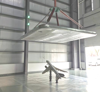
- Impulse Current Test Systems
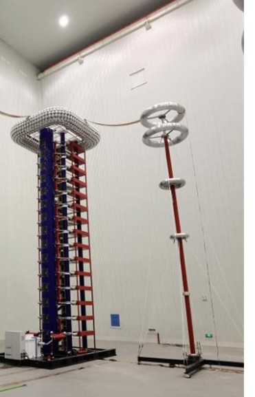
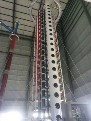
- Impulse Voltage Test Systems
- Partial Discharge Test System
- Resistors
- Transformer Test Falicilites
- Other Test Instrument
- Voltage Divider
- Variable Inductance AC Resonant Test Systems
- Variable Frequency AC Resonant Test Systems
- News & Events
- Downloads
- Contact Us